Feeding my tropical fish
I recently got a new tropical fish tank and, of course, wanted to make maintaining it a little easier. I initially bought an automatic fish feeder, but it only worked with granules which my fish wouldn’t eat, they liked flakes only.
I stumbled across an interesting project on Thingiverse and it looked really good, so I downloaded the files, printed them out and bought a SG90 servo motor for £3 - the first time I’ve used a servo. What I really liked about this design was that it was able to feed flakes!
Thankfully, the author had created not only a very good printable, but also provided a youtube video showing how it worked, and some code. The only problem was the code was for a single board - the ESP32CAM and had written firmware specifically for it.
Being a big time fan of ESPHome, and with 14 ESPs dotted around my property, I wanted to use that for this instead. I already had one automating the fishtank lights and measuring temperature. Turns out I was able to plug this straight into that.
I was very pleased that this whole project was very smooth to get working and is now reliably feeding my fish.
As the original instructions didn’t cater for Esphome, I’ve written a guide on how I got this working. Good luck!
ESPHome instructions for nahueltaibo/fish-feeder
This project can also work very smoothly with ESPHome and the ESP8266, as well as the ESP32 range.
Print and assemble the kit exactly as described;
When assembled, you should have the SG90 servo motor fitted, with the wires emerging from the hole in the base. You may need to extend the wires to reach your ESP.
Connect to your ESP8266
- Red Wire = 5v. This also operates on 3.3v directly to your ESP chip. Connect either to a 5v feed, or to one of the 3.3v pins on the ESP8266
- Brown Wire = GND. Connect this to one of the GND pins on your ESP8266
- Orange (or Yellow) Wire = Signal. Connect this to your chosen signal pin. Choose from one of the following pins, which support PWM control
- D1 (GPIO5)
- D2 (GPIO4)
- D5 (GPIO14)
- D6 (GPIO12)
- D7 (GPIO13)
(ESP32 connection is almost identical, but ensure your chosen signal pin is PWM capable)
The Yaml code block for the device, assuming you are using pin D1 from the above, would be:
output:
  - platform: esp8266_pwm
    id: pwm_output
    pin: D1
    frequency: 50Hz

servo:
  - id: my_servo
    output: pwm_output

number:
  - platform: template
    name: "Feeder Servo"
    min_value: -100
    initial_value: 0
    max_value: 100
    step: 1
    optimistic: true
    set_action:
      then:
        - servo.write:
            id: my_servo
            level: !lambda 'return x / 100.0;'
Explanation: This tells ESPHome that the ESP8266 has a servo connected to D1, and to create a number slider in Home Assistant with a range of -100 through +100
Now compile and flash your ESP8266 in your normal way.
I use esphome on linux, but there are many ways to do this, including through the browser.
The logs after it restarts should contain some strings similar to
[20:41:02.132][C][esp8266_pwm:021]: ESP8266 PWM:
[20:41:02.132][C][esp8266_pwm:021]:   Frequency: 50.0 Hz
[20:41:02.132][C][esp8266_pwm:152]:   Pin: GPIO12
[20:41:02.132][C][template.number:016]: Template Number 'Feeder Servo'
[20:41:02.132][C][template.number:049]:   Optimistic: YES
[20:41:02.132][C][template.number:453]:   Update Interval: 60.0s
[20:41:02.133][C][servo:014]: Servo:
[20:41:02.133][C][servo:014]:   Idle Level: 7.5%
[20:41:02.133][C][servo:014]:   Min Level: 3.0%
[20:41:02.133][C][servo:014]:   Max Level: 12.0%
[20:41:02.133][C][servo:014]:   Auto-detach time: 0 ms
[20:41:02.133][C][servo:014]:   Run duration: 0 ms
Now in Home Assistant, under Integrations -> ESPHome -> Your ESP8266, you should see something like this;
Slider
Moving the slider should move the servo to the correct position. For me, -100 has the hole positioned inside the silo, and +100 moves it above the drop hole.
If that’s working for you, you can move onto automations.
Suggested automations
To ease with automations, I created a “Helper” in Home Assistant of type “Input Button”
Helper button
This can be used on a dashboard to create a button, like so:
Helper Button
Feed Fish button
A full automation might look something like the following.
Example Fish Feeding Automation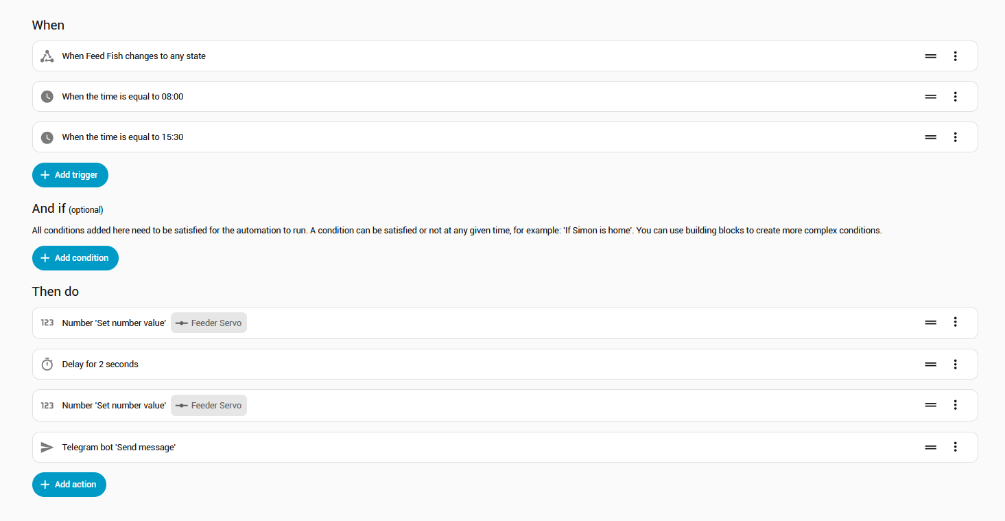
-
First trigger is the above button, so I can feed manually, and this also operates twice during the day by schedule
-
First Action is to set the number to
100to move the disk above the drop hole. Then it pauses for 2 seconds and then moves the disk back under the flakes to pick up a new load. Then it sends me a Telegram so I know it’s worked. The time on the above dashboard button also updates automatically to show when it was last used.
The entire yaml for this automation is:
alias: Feed Fish
description: ""
triggers:
  - trigger: state
    entity_id:
      - input_button.feed_fish
    to: null
  - trigger: time
    at: "08:00:00"
  - trigger: time
    at: "15:30:00"
conditions: []
actions:
  - action: number.set_value
    metadata: {}
    target:
      entity_id: number.fishtankesp01_feeder_servo
    data:
      value: "100"
  - delay:
      hours: 0
      minutes: 0
      seconds: 2
      milliseconds: 0
  - action: number.set_value
    metadata: {}
    target:
      entity_id: number.fishtankesp01_feeder_servo
    data:
      value: "-100"
  - action: telegram_bot.send_message
    metadata: {}
    data:
      title: Fish fed!
      message: The fish have been fed
mode: single
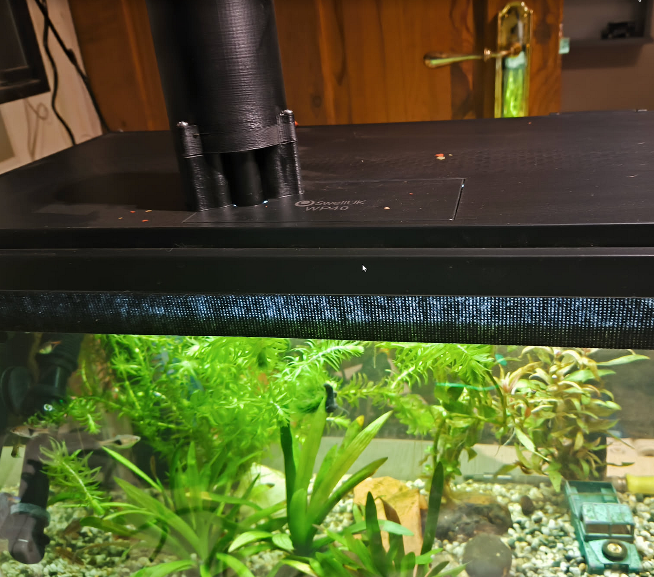
Feeder atop the tank